IntroductionJelly2 series smart industrial cameras are mainly designed for machine vision and various image acquisition areas. The cameras are very compact, occupy a very small space, can be used on machines or solutions which have limit space. Resolution from 0.36MP to 5.0MP, speed upto 110fps, support global shutter and rolling shutter, support opto-couplers isolation GPIO, support multi-cameras work together, compact and light.
Features1. 0.36MP, 5.0MP resolution, total 6 models mono/color industrial digital camera;
2. USB2.0 interface, up to 480Mb/s, Plug and play, no need external power supply;
3. Provide completed API for users' secondary development, provide Demo Source Code, Support VC, VB, DELPHI, LABVIEW and other development language;
4. Support firmware upgrade on-line;
5. Support Windows XP / Vista / 7 / 8/10 32&64 bit Operation System, can customize for Linux-Ubuntu, Android Operation System;
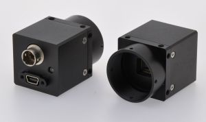
6. CNC processed precision aluminum alloy shell, size is 29mm×29mm×30mm, net weight: 35g;
7. Board camera is available.
ApplicationJelly2 series industrial cameras are mainly designed for machine vision and various image acquisition areas. They are mainly used for following areas:
Medical and life sciences Area
- Microscope Imaging
- Medical diagnosis
- Gel Imaging
- Live Cell Imaging
- Ophthalmology and iris imaging
Industrial Area
- Electronics and semiconductor inspection
- Visual positioning(SMT/AOI/Glue dispenser)
- Surface defect detection
- 3D scanning machine
- Printing quality inspection
- Food and medicine bottles inspection
- Robot welding
- Tag OCR/OCV identification
- Robot arm visual positioning
- Industrial production line monitoring
- Vehicle wheel alignment machine
- Industrial Microscope
- Road toll and traffic monitoring
- High speed vehicle plate image capture
Public security and investigation
- Biometrics
- Fingerprint, palm print image capture
- Facial recognition
- License image capture
- Documents and notes image capture and identification
- Spectroscopy testing equipment
Specification
| Model |
MUC36M/C(MGYYO) |
MUC36M/C(MRYYO)-H |
MUC500M/C(MRYYO) |
| Sensor Model |
Aptina MT9V034 |
Aptina MT9V034 |
Aptina MT9P031/006 |
| Color |
Mono/Color |
Mono/Color |
Mono/Color |
| Image Sensor |
NIR Enhancing CMOS |
NIR Enhancing CMOS |
CMOS |
| Sensor Size |
1/3" |
1/3" |
1/2.5" |
| Effective Pixels |
0.36MP |
0.36MP |
5.0MP |
| Pixel Size |
6.0μm×6.0μm |
6.0μm×6.0μm |
2.2μm×2.2μm |
| Sensitivity |
4.8V/lux-sec |
4.8V/lux-sec |
1.4V/lux-sec |
|
Max. Resolution
|
752 × 480 |
752 × 480 |
2592 × 1944
|
| Frame Rate |
60fps |
110fps |
9fps |
| Exposure Mode |
Global Shutter
|
Global Shutter
|
Rolling Shutter
|
| Dot Frequency |
27MHz |
27MHz |
48MHz |
| Dynamic Range |
55dB~100dB |
55dB~100dB |
70.1dB |
| Signal Noise Rate |
>45dB |
>45dB |
38.1dB |
| Frame Buffer |
32MB Frame buffer |
| Scan Mode |
Progressive Scan |
| Spectral Response |
400nm~1000nm
|
| Input & Output |
Optocoupler isolation GPIO, 1 of external trigger input, 1 of flash light output, 1 of 5V input/output |
| White Balance |
Auto / Manual |
| Exposure Control |
Auto / Manual |
| Main Function |
Image preview, image capture(bmp, jpg, tiff), Video record(compressor is optional) |
| Programmable Control |
Preview FOV ROI, Capture FOV ROI, SKIP/Binning mode, Contrast, Brightness, Saturation,
Gamma value, RGB color gain, exposure, dead pixels remove, focus evaluation, custom serial number (0 to 255)
|
| Data Output |
Mini USB2.0, 480Mb/s |
| Power Supply |
USB2.0 Power Supply, 200-300mA@5V |
| Compatible Interface |
ActiveX, Twain, DirectShow, VFW |
| Image Format |
Support 8bit, 24bit, 32bit image preview and capture, save as Jpeg, Bmp, Tiff format |
| Operation System |
Windows XP/VISTA/7/8/10 32&64 bit OS (can customize for Linux-Ubuntu, Android OS)
|
| SDK |
Support VC, VB, C#, DELPHI developing Language; OPENCV, LABVIEW, MIL thirty-parties' machine vision software |
| Lens Interface |
Standard C-Mount ( CS and M12 mount are optional) |
|
Work Temperature
|
0°C~60°C |
|
Storage Temperature
|
-30°C~70°C |
| Camera Dimension |
29mm×29mm×30mm((C-mount is not included)) |
| Module Dimension |
27mm×27mm×22mm |
| Camera Weight |
35g |
| Accessories |
Equipped with standard infrared filter(not available in mono camera), 2m USB cable with fix screws, 6-pin Hirose GPIO connector, 1 CD with software and SDK. |
| Box Dimension |
118mm×108mm×96mm (length × width × height) |
 Dimension
 GPIO Trigger interface introduction
| Trigger Serial No |
1 |
2 |
3 |
4 |
5 |
6 |
| Cable Color |
Red |
Black |
Yellow |
White |
Gray |
Brown |
| Function |
5V OUT/5V IN |
GND |
TRIGGER_IN+ |
TRIGGER_IN- |
FLASH_OUT_C |
FLASH_OUT_E |
Power SupplyThe camera is powered by USB2.0
BUS POWER, the power supply is 5V@500mA, The BUS POWER provide power supply to the camera, at the same time, it provides power supply via diode SMB540, the power is about 200mA@5V.

GPIO Input Interface
The following figure is the schematic diagram of external trigger input, the inputted signal has been insulated by opto-coupler TLP281.

TLP281 conversion performance
The camera's internal optocoupler VCC = 5V, If IF = 16mA, then the external trigger input Rising edge Delay is 2us, Falling edge Delay is 25us;
When using "TRIGGER_IN +" as trigger source, the trigger electrical level range is 0V- + 5V. If the trigger source electrical level is out of this range, an external current limiting resistor should be connected, the optocoupler works under current of 10mA. Limiting resistor is calculated as follows:
R = 100 x ( Vin - 0.7 ) - R0
Vin is Trigger source electrical level
R0 is The camera's internal series resistor 200 Ohm
R is the required external series resistor.
Under normal temperatures (0- + 50 degrees) , the maximum operating current of the optocoupler is 50mA, standard operating current is 10mA, if it exceeds the maximum allowable current, optocouplers may be burned.

GPIO Output Interface (control flashlight)
For some flash light which has Rising edge input (We can measure the flash light pin to determine whether there is a Rising edge input, if we have measured a pin has electrical level signal, it can be judged there is Rising edge electrical level internal the flash light, such as the K-150A models flash light, one of the synchronous trigger pin end is + 5V, and the other end is GND), you can use the connection diagram below:

 Company Profile